
Chemical Earthing – Complete Guide
Chemical Earthing is one of the most effective grounding systems used to provide
low earth resistance and protect electrical equipment, buildings, and personnel
from electrical faults and lightning strikes. This guide explains everything
about chemical earthing, including its types, design, installation, testing,
advantages, and applications.
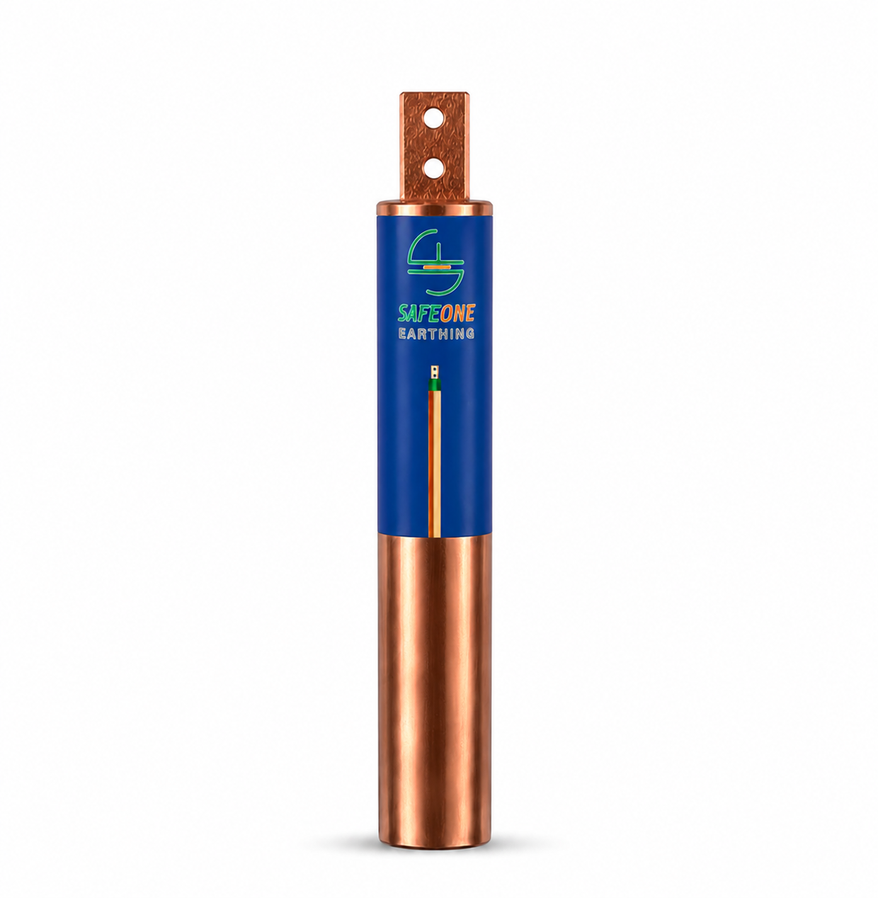
Table of Contents
Introduction to Chemical earthing
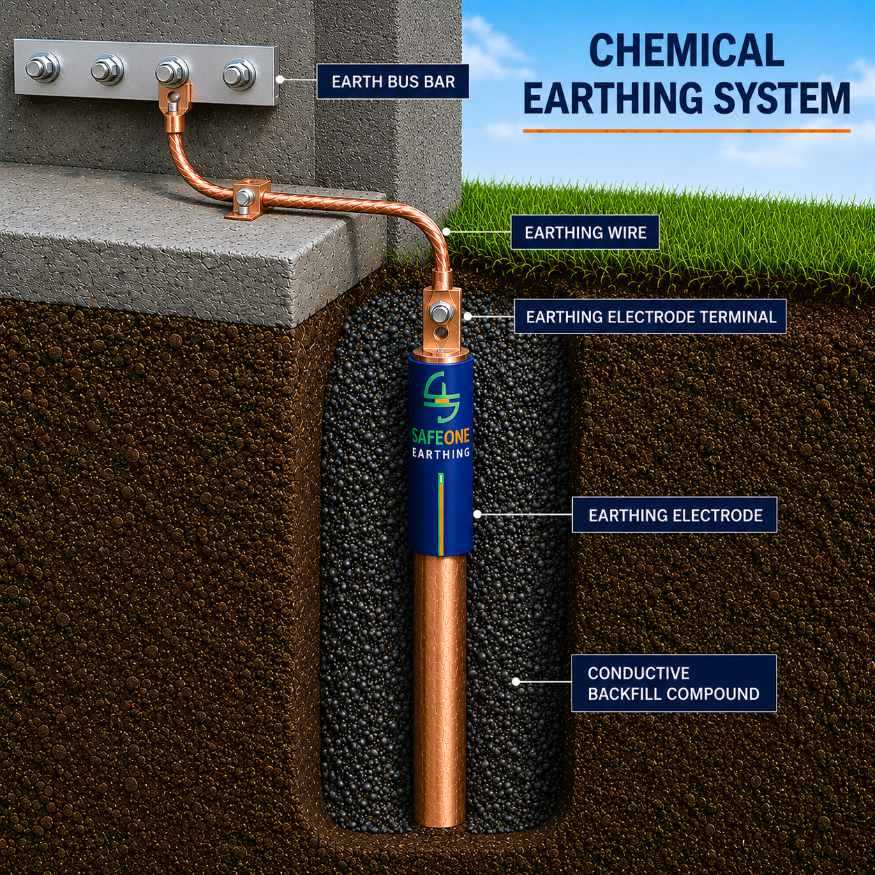
Chemical Earthing rods are used for electrical systems in earthing applications in this earthing ground enhancement compound is used while the conventional earthing uses salt and charcoal. Ground enhancement compounds are excellent Earthing Design conductive compounds. It is a mixture of bentonite graphite and Carbon compounds also called chemical earthing compound or backfill compound (BFC). Mixed with water forming a paste which is poured in the earth pits. These compounds surround the electrode. Surrounding the Electrode with BFC increase the ground rod's surface area and decreasing ground resistance. Ground enhancement compounds are widely used for poor soil conductivity in Rocks and mountain areas. This compound is highly conductive, which reduces the resistivity of ground and helps in quick discharge of fault current. Chemical earthing rods are maintenance free earthing which does not require any water during the complete life span of earthing rod. This earthing has a long life as compared to conventional earthing and is very easy to install. The ohmic value is retained that is not changed throughout its useful life.
Chemical earthing is particularly effective in rocky, sandy, dry, and mountainous soil where conventional earthing systems often fail to achieve the required resistance value.
Modern chemical earthing electrodes are manufactured using GI, Copper Bonded Steel, or Pure Copper with protective coatings ranging from 100 to 250 microns
What is Chemical Earthing?
Chemical earthing is an advanced grounding system designed to provide a low-resistance path for electrical fault currents to safely flow into the earth. It helps protect people, electrical equipment, and buildings from electric shocks, short circuits, and lightning strikes. Various mixtures are used in chemical earthing, including carbon-based or bentonite-based materials combined with graphite and other compounds. Some mixtures also contain conductive cement, which hardens into a concrete-like form after installation, remaining intact without mixing with the soil or being washed away.
Types of Chemical Earthing
GI Earthing Rod
Strip in pipe earthing rods are electrodes having pipe and strip GI strip inserted inside the pipe at the top of the strip terminal are welded to which earthing strip is connected. Galvanized iron earthing rods (GI) are zinc coated that helps to prevent corrosion.GI earthing rods are most economical and widely used.
Pipe In Pipe Earthing Rod
- Pipe in pipe earthing rods have an inner pipe surrounded by an external pipe.
- These rods are very robust in construction Dual pipe increases the surface area of the rod capable of withstanding heavy short circuit current.
- The inner pipe is covered by the outer pipe and is not exposed to the outside soil or in direct contact, so it will not rust.
- Filled with conductive compound between pipes to withstand heavy short circuit current.
- Can be customized as per requirement.
- Sizes available 50mm and 80mm length 1/2/3 metre
- They are much more costly than GI or copper bonded rods mostly used in high corrosive environments.
- These rods are lifetime once installed properly.
Solid Earthing Rod
- Solid earthing rod is light in weight and easy to install V clamp or T clamp welded on top for earthing strip connections.
- The V clamp has 4 holes, and the T clamp has 2 holes on both sides of the clamp for strip connections.
- Copper coated on MS material up to 100 to 250 microns
- Solid earthing rods can be driven deeply by using a coupler up to 3-6-9 mtr or deeper using a coupler on both ends of the rod.
- This earthing can be customized as per the requirement
- Sizes available 14.2/17.2/25/32mm length 1/2/3 metre.
Copper Bonded Earthing Electrode
- Copper bonded earthing rods are coated with a copper layer. that increases the conductivity and the life of earthing, it also increases the current carrying capacity of fault current.
- Sizes available 50mm and 80mm length 1/2/3 metre
- Copper plating with thickness of 100 to 250 microns.
Pure Copper Earthing Electrode
- Pure copper earthing rods are available in solid electrode or plate type.
- They are much more costly than GI or copper bonded rods mostly used in high corrosive environments.
- These rods are lifetime once installed properly.
- Pure copper earthing rods are available in solid electrode or plate type.
- They are much more costly than GI or copper bonded rods mostly used in high corrosive environments.
- These rods are lifetime once installed properly.
Pure Copper Earthing Electrode
- The solid earthing rod is lightweight and easy to install, featuring either a V clamp or T clamp welded on top for earthing strip connections. The V clamp has four holes, while the T clamp has two holes on each side for strip connections. Made from MS material with a copper coating of 100 to 250 microns, these rods can be driven deep into the ground using a coupler, reaching depths of 3, 6, or 9 meters, or even deeper with couplers on both ends. They can be customized as needed and are available in sizes of 14.2, 17.2, 25, or 32 mm with lengths of 1, 2, or 3 meters.
Which Chemical Is used in Earthing
- There are numerous available mixtures used in chemical earthing this are carbon based, or bentonite based with a mixture of graphite and other compounds
- Conductive cement is also present in some compounds. after installation it hardens into a concrete that does not mix with the ground and is not washed out.
Chemical Earthing Design
The best protection for a system comes from earthing systems designed to meet proper standards. This involves selecting the right earthing rod, considering its diameter, length, and the number of electrodes installed. A soil resistivity test can help design the earth rods by determining the soil’s resistivity in ohm-meters. The number of rods needed depends on the electrical load, short circuit, fault current, and the soil’s resistivity, which is influenced by moisture and temperature. Earthing design calculations follow standards like IS 3043, IEC 60364, and BS 7430. According to section 10.3 of IS 3043, the permissible current density at the earth electrode is Id = 7.57×10³/√(ρ×t) Amps/m², where ρ is soil resistivity and t is fault clearance time. The resistance for a plate-type electrode is R = ρ/4 × (π/A) Ω, with A being the total electrode area. Fault currents must be safely discharged to earth to prevent electric shock. Chemical earthing electrodes, made from high-quality mild steel coated with zinc or copper and filled with backfill compound, offer very low resistance and can quickly discharge fault currents.
How to Achieve Earth Resistance Below 1 ohm
- Increasing the rod’s surface area by extending its length and diameter and driving it deep into the ground—up to 3 meters or more—can greatly reduce ground resistivity for better results. Connecting two or more rods lowers resistance even further. Treating the soil with high-quality backfill compound also helps. Using a proper conductor size, typically one size larger, is recommended. Since resistance largely depends on soil conditions, it’s important to improve them through proper design.
Chemical Earthing Installation Procedure
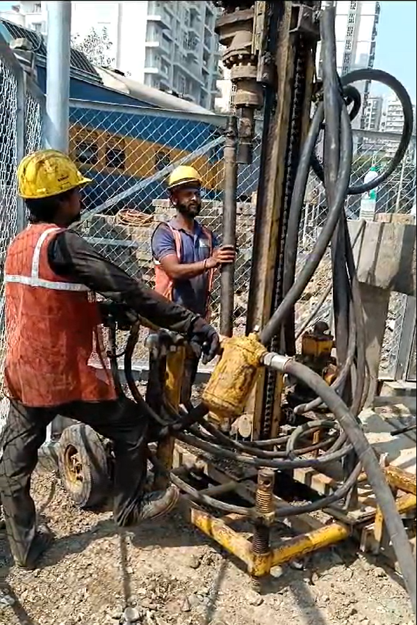
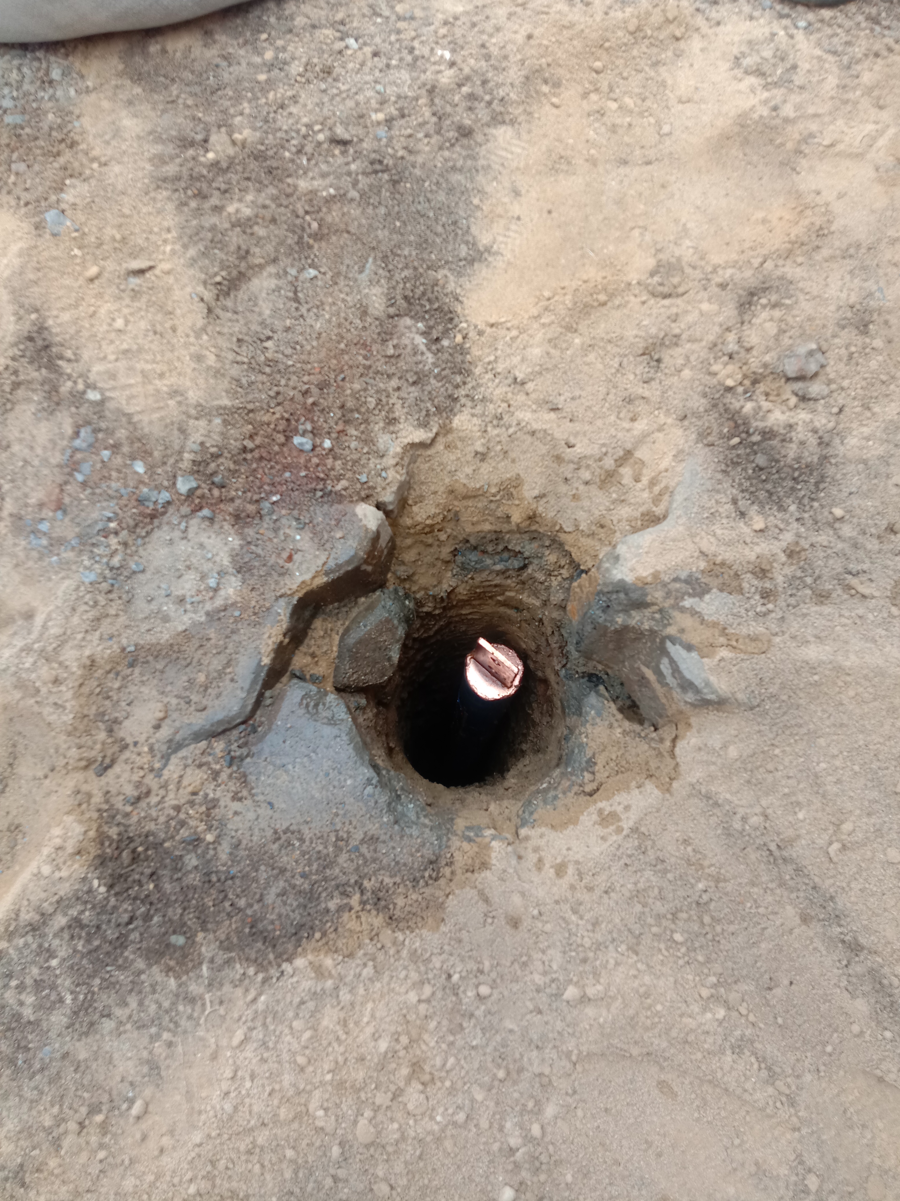
For installing a 3-meter electrode, a vertical hole needs to be drilled below ground using a boring machine as shown in Image -01 with a 100–125 mm bore.
The earthing boring machine is typically paired with a compressor housed inside a vehicle.
A movable tripod machine with three supports, wheels for mobility, and a motor mounted at the top is assembled on-site.
Once assembled, it’s connected via a pipe to the compressor, which operates using hydraulic or air pressure from the vehicle.
After assembly, the proper location should be identified, ensuring no MEP services run underground where the earthing will be done.
The drill bit, chosen according to the hole diameter, is fixed in the tripod machine.
Once the compressor is started, it powers the tripod machine, rotating the drill bit to bore vertically to the required depth.
After drilling, insert the earthing electrode as shown on figure -02,
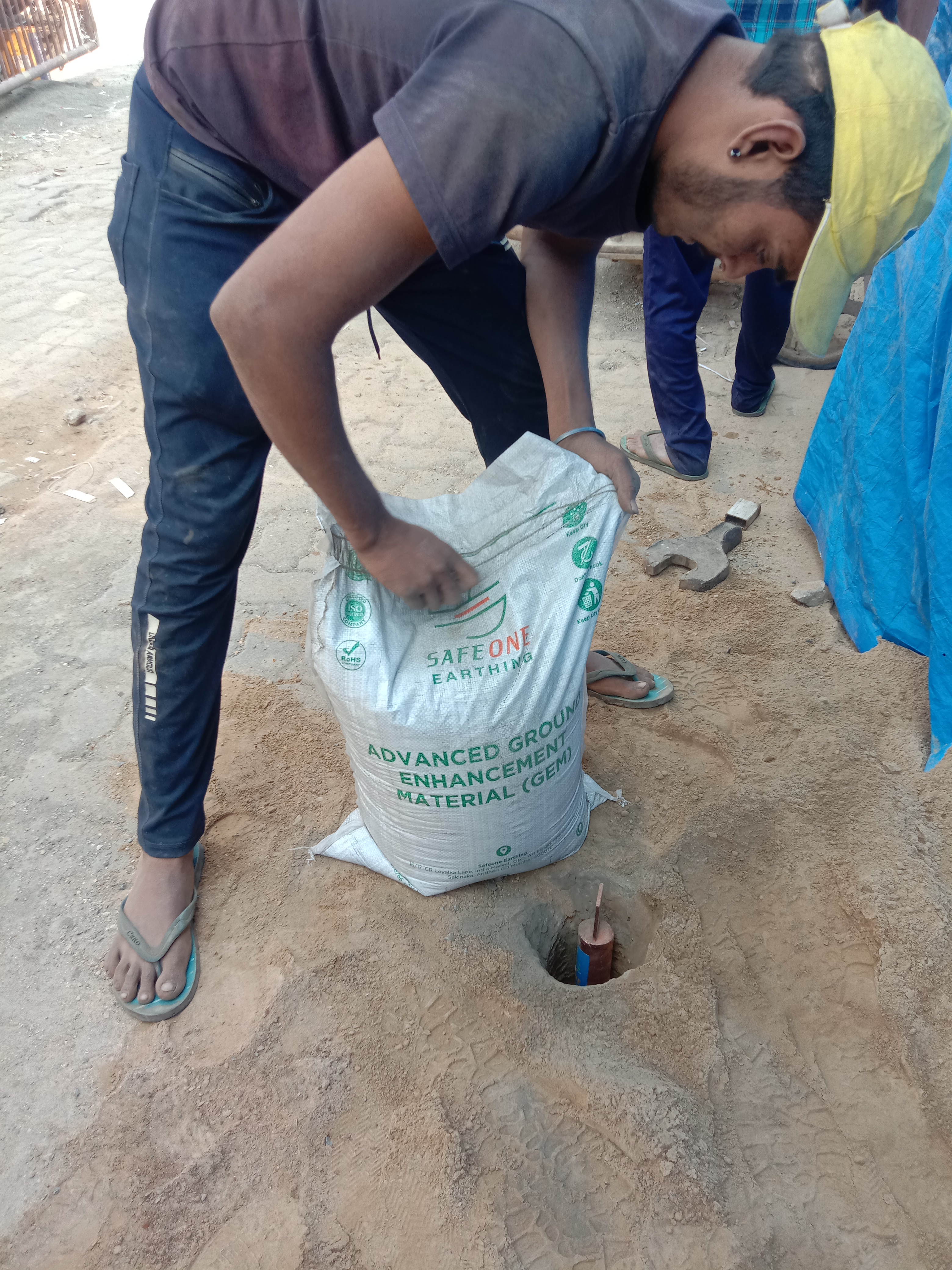
prepare the ground enhancement compound and pour it in with water inside the surrounding gap of the hole as shown in figure-03.
Finally, connect the earthing strip to the electrode terminal, install the chamber, and measure the earth resistance.
Chemical Earthing Testing
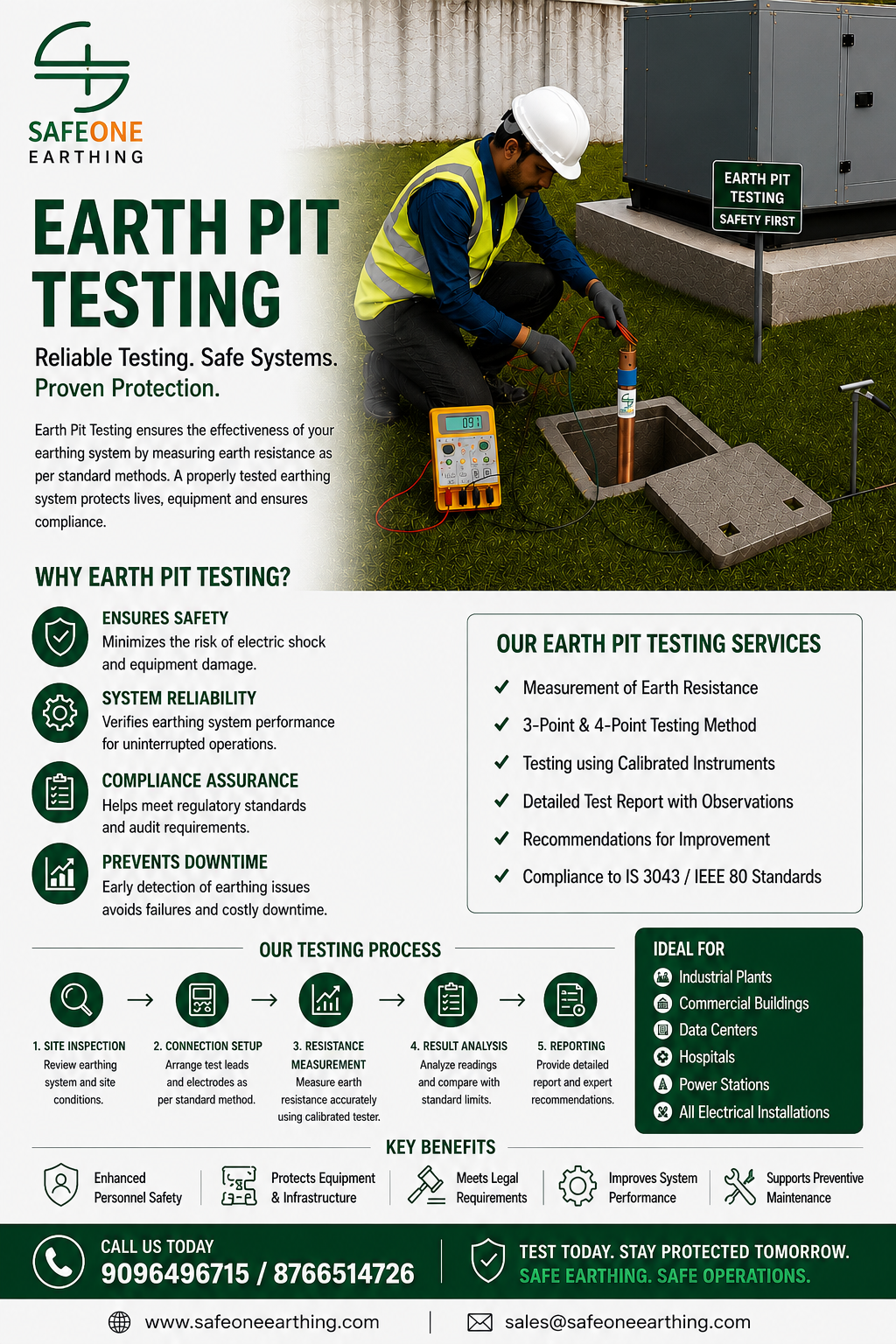
Earth pit Testing is essential once in a year to check the resistivity of earthing if the earthing resistivity is high any fault occurs in the system Creates Fault Current.This Fault current may not be discharged quickly if earthing is weak or not properly done hence possibility of system failure is there to minimize unwanted shut down it’s a good Practice to have yearly checking of your earth pits.Testing for earthing rod is done using earth resistance tester.3-point testing method are most commonly used.
Applications of Chemical Earthing
electrical panels.
transformers to substations and DG sets.
It covers factories.
commercial and residential buildings.
solar plants.
hospitals, data centers.
telecom towers, railways.
lightning arresters.
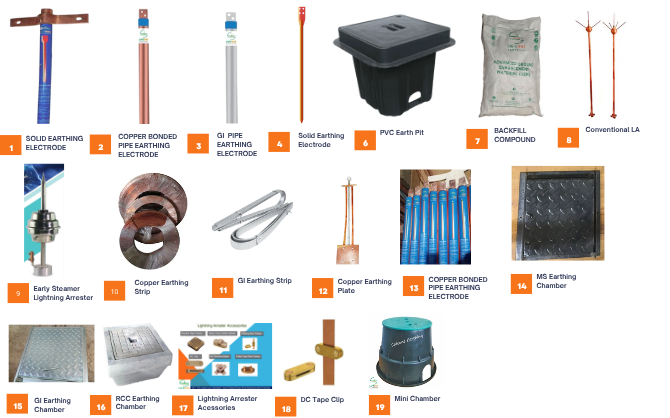
Chemical Earthing Material
Advantages of Chemical Earthing
Maintenance Free Chemical Earthing: -
Chemical earthing is maintenance-free because it doesn’t require water, unlike conventional earthing. The backfill compound used doesn’t mix with the soil, so the earthing value stays consistent. Acting like a metal rod, the compound doesn’t dissolve in the soil, eliminating the need for watering, unlike conventional earthing where salt and charcoal dissolve over time.
No Water Required: -
Chemical earthing doesn’t require water because the backfill compound functions like metal, encasing the earthing electrode.
Easy To Install: -
Installation is much simpler than with conventional earthing, as it can be done by machine or manually by drilling a 100–125mm diameter hole. The chemical earthing electrode is smaller in size compared to conventional earthing plates, which are usually 300x300mm or 600x600mm. Installing these larger plates means digging out a bigger area, while chemical earthing only needs a small round hole. This makes the process faster, requires less manpower, and cuts both cost and time, all while providing a reliable earthing system.m.
Good Conductivity: -
Chemical earthing offers excellent conductivity compared to conventional methods. When properly installed with a backfill compound, the compound firmly surrounds the electrode, increasing its surface area. This not only boosts conductivity but also enhances its ability to withstand high short-circuit currents.
Less space required: -
Chemical earthing is space-efficient, with a smaller width compared to conventional earthing. It can be installed vertically into the ground as needed, up to 3 to 6 meters deep. Thanks to these advantages, it’s ideal for use in areas where space is limited.
Chemical earthing has a lower ohm value than conventional earthing. Certain CNC machine panels, printing press machines, and sophisticated electronic panels require a neutral and earthing voltage below 2 volts, which is difficult to achieve and only possible with a low-ohm earthing electrode. This is usually achieved by installing chemical earthing, as it offers very low resistance to earth, especially when used with BFC compound.
Chemical earthing lasts a long time when the right materials are chosen. Copper-bonded rods and GI rods are most commonly used, with coatings applied to the base material to prevent rusting and extend the electrode’s life. Stainless steel and pure copper can also be used for even greater durability.
Chemical earthing can handle heavy current which supports the electrode in quickly discharging high current. This works best when the BFC compound is properly packed around the electrode, acting like a metal to increase the surface area and ensure good conductivity for efficiently releasing fault current.
Chemical earthing maintains a consistent resistance value for many years because it doesn’t rely on salt and charcoal to improve earth resistance. Over time, salt and charcoal mix with the soil and lose effectiveness in reducing resistance. In contrast, chemical earthing uses a BFC compound that lasts much longer, helping the earth electrode maintain its resistance value for an extended period.
Chemical Earthing VS Conventional Earthing
| Chemical Earthing | Conventional Earthing |
| Maintenance-free and no watering needed. | Needs periodic watering to maintain the resistance value. |
| Lower earth resistance compared to conventional earthing. | Higher resistance in a new installation compared to chemical earthing. |
| Easy to install with minimal manpower since the installation is carried out by a boring machine. | More manpower is needed for the installation since it has to be done manually. |
| Can be driven deep into the ground with a jointing coupler measuring 6 to 9 meters or more. | It’s tough to dig deeper than 3 meters by hand. |
| The low earth resistivity of the rod is maintained throughout its entire lifespan. | Resistivity value changes over the lifespan. |
Chemical Earthing Diagram and Drawings
Chemical Earthing Diagram Drawings Click to Download PDFFrequently Asked Questions
Chemical Earthing is an advanced grounding system that maintains low earth resistance by using conductive compounds around the electrode.
The conductive backfill compound used in Chemical Earthing typically consists of specially formulated conductive minerals, graphite, carbon-based compounds, and moisture-retaining materials such as bentonite. These materials surround the earthing electrode, creating a highly conductive path that helps maintain low earth resistance for many years while reducing corrosion and minimizing maintenance requirements.
It protects electrical equipment, prevents electric shocks, improves system safety, and ensures efficient fault current dissipation.
No. A properly installed Chemical Earthing system does not require regular watering. The conductive compound surrounding the earthing electrode acts as a highly conductive medium, maintaining a low earth resistance value for a long period. Unlike conventional earthing systems that may depend on moisture, the chemical backfill provides stable electrical conductivity and long-lasting performance with minimal maintenance.
Chemical earthing uses an advance conductive backfill compound around the electrode to improve conductivity and help maintain low earth resistance. Normal conventional earthing generally relies on salt charcoal around the electrode to maintain the resistance..
Properly designed chemical earthing generally requires No maintenance, but periodic inspection and earth resistance testing are still recommended.
With proper installation and quality materials, a Chemical Earthing system can last for more than 10 years with minimal maintenance.
Yes. Safeone Earthing LLP provides complete supply, installation, testing, and maintenance of earthing and lightning protection systems.