

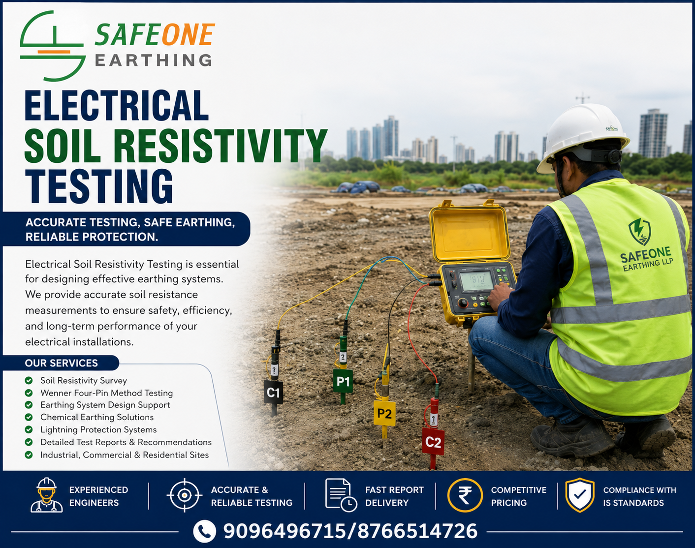
Electrical Soil Resistivity Testing: Complete Guide to Accurate Earthing System Design
Introduction
Electrical safety begins below the ground. Before installing any earthing system, it is essential to understand the electrical properties of the soil. Electrical Soil Resistivity Testing is the process of measuring the resistance offered by the soil to the flow of electrical current. The test helps engineers design an efficient earthing system that ensures personnel safety, equipment protection, and compliance with national and international electrical standards.
At Safeone Earthing LLP, we provide professional Soil Resistivity Testing using the Wenner Four Pin Method to determine the most suitable earthing design for industrial, commercial, residential, utility, and infrastructure projects.
What is Soil Resistivity?
Soil resistivity is the measure of how strongly soil resists the flow of electric current. It is expressed in Ohm-meter (Ω·m).
Different types of soil have different resistivity values depending on several environmental conditions. Measuring soil resistivity before installing an earthing system helps determine:
- Number of earth electrodes required
- Depth of installation
- Type of earthing system
- Electrode spacing
- Ground enhancement material requirements
- Expected earth resistance
Why is Soil Resistivity Testing Important?
A properly designed earthing system depends on accurate soil resistivity measurements.
Benefits include:
- Accurate earthing system design
- Improved electrical safety
- Better lightning protection performance
- Reduced equipment damage
- Compliance with electrical standards
- Lower installation costs
- Longer earthing system life
- Reduced maintenance requirements
Without soil resistivity testing, an earthing system may fail to achieve the required earth resistance.
Applications of Soil Resistivity Testing
Electrical Soil Resistivity Testing is widely used for:
- Industrial Plants
- Commercial Buildings
- Residential Projects
- Power Plants
- Electrical Substations
- Solar Power Plants
- Wind Farms
- Telecommunication Towers
- Data Centers
- Hospitals
- Schools and Colleges
- Airports
- Railways
- Oil & Gas Industries
- Manufacturing Plants
- Water Treatment Plants
Factors Affecting Soil Resistivity
Several environmental and geological factors influence soil resistivity.
1. Soil Type
Different soils conduct electricity differently.
Examples:
- Clay Soil – Low Resistivity
- Sandy Soil – High Resistivity
- Rocky Soil – Very High Resistivity
- Loamy Soil – Moderate Resistivity
2. Moisture Content
Higher moisture content significantly reduces soil resistivity.
Dry soil increases resistance.
3. Temperature
Cold soil or frozen ground has higher resistivity than warm soil.
4. Salt Content
Higher dissolved salts improve conductivity and lower resistivity.
5. Soil Layering
Different underground layers may have different resistivity values, affecting earthing design.
Methods of Soil Resistivity Testing
Several testing methods are available, including:
- Wenner Four Pin Method
- Schlumberger Method
- Driven Rod Method
The Wenner Four Pin Method is the most commonly used due to its simplicity and accuracy.
Wenner Four Pin Method
The Wenner Method uses four equally spaced electrodes driven into the ground.
A controlled electrical current is injected through the outer electrodes, while the voltage drop is measured between the inner electrodes.
The measured values are used to calculate soil resistivity.
Advantages
- Highly accurate
- Simple procedure
- Suitable for most soil conditions
- Standardized internationally
- Reliable for earthing system design
Equipment Used
Professional testing generally requires:
- Earth Resistivity Tester
- Four Test Electrodes
- Test Leads
- Measuring Tape
- Hammer
- GPS (optional)
- Data Recording Sheet
- Personal Protective Equipment (PPE)
Testing Procedure
Step 1
Select the testing location.
Step 2
Insert four electrodes into the ground at equal spacing.
Step 3
Connect the electrodes to the earth resistivity tester.
Step 4
Inject current through the outer electrodes.
Step 5
Measure the voltage between the inner electrodes.
Step 6
Record the readings.
Step 7
Repeat the test with different electrode spacings to assess deeper soil layers.
Step 8
Analyze the results for earthing system design.
Soil Resistivity Formula
The Wenner method calculates apparent soil resistivity using:
ρ = 2πAR
Where:
- ρ = Soil Resistivity (Ω·m)
- A = Electrode Spacing (m)
- R = Measured Resistance (Ω)
- π = 3.1416
The calculated values help determine the most effective earthing configuration.
Interpreting Test Results
General guideline:
| Soil Resistivity (Ω·m) | Soil Condition |
|---|---|
| Less than 20 | Excellent |
| 20–50 | Good |
| 50–100 | Moderate |
| 100–500 | Poor |
| Above 500 | Very Poor |
Actual values vary depending on project requirements and site conditions.
Standards Followed
Professional Soil Resistivity Testing is typically performed in accordance with:
- IS 3043 – Code of Practice for Earthing
- IEEE Std 81 – Guide for Measuring Earth Resistivity
- IEC 60364 – Low Voltage Electrical Installations
- IEEE 80 – Guide for Safety in AC Substation Grounding
Why Perform Soil Resistivity Testing Before Earthing Installation?
Testing before installation helps:
- Reduce project costs
- Avoid overdesign or underdesign
- Select the correct earthing method
- Improve fault current dissipation
- Increase personnel safety
- Enhance lightning protection
- Improve equipment reliability
Common Mistakes to Avoid
- Skipping soil testing before installation
- Using incorrect electrode spacing
- Testing only one location on large sites
- Ignoring seasonal moisture variations
- Using uncalibrated equipment
- Misinterpreting test results
Why Choose Safeone Earthing LLP?
Safeone Earthing LLP provides reliable and professional Soil Resistivity Testing services using advanced equipment and industry best practices.
Our Services
- Soil Resistivity Testing
- Earth Pit Testing
- Earthing System Design
- Chemical Earthing Installation
- Plate & Pipe Earthing
- Lightning Protection Systems
- Electrical Safety Testing
- Electrical Design & Drafting
- Earthing System Revamping
- Testing & Commissioning
Why Clients Choose Us
- Experienced Engineers
- Accurate Site Analysis
- Latest Earth Resistivity Testers
- Standards-Compliant Procedures
- Detailed Test Reports
- Cost-Effective Solutions
- On-Time Service
- Support Across Industrial, Commercial, and Residential Projects
Conclusion
Electrical Soil Resistivity Testing is the foundation of an effective earthing system. By measuring the soil's electrical characteristics before installation, engineers can design safer, more reliable, and cost-effective grounding systems. Whether for an industrial plant, commercial complex, solar project, or residential development, conducting a soil resistivity survey is a critical step toward ensuring electrical safety and long-term system performance.
Safeone Earthing LLP offers professional Soil Resistivity Testing, Earth Pit Testing, Earthing System Design, and Lightning Protection Solutions to help you build safe and standards-compliant electrical infrastructure.